Dino-Game
Joystick Setup Configuration 🎮
Before to do the configuration on STM32CubeMX take a look of all pin configurations in this table
1. Connecting Joystick Sensor to STM32 board
| Joystick Pin | STM32 Board Pin > Pin CubeMX Config | Connection Diagram |
|---|---|---|
| VRx | A5 > PC_0 | 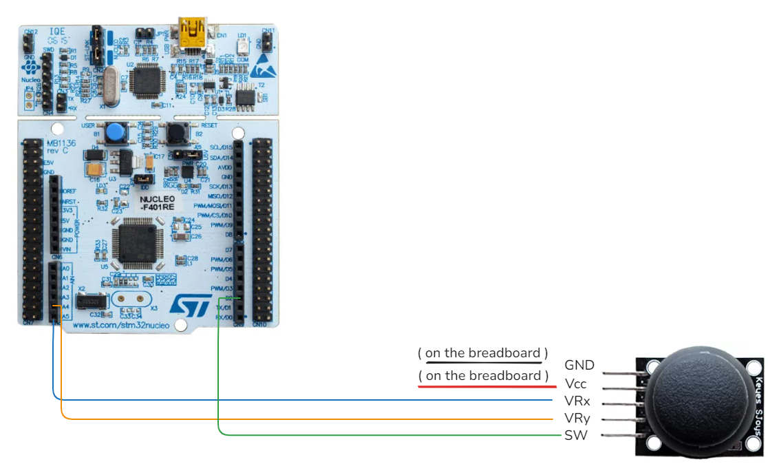 |
| VRy | A4 > PC_1 | |
| SW | D2 > PA_10 | |
| GND | GND pin of Board |
2. Configure ADC1 with two channels
- Navigate to the section Analog
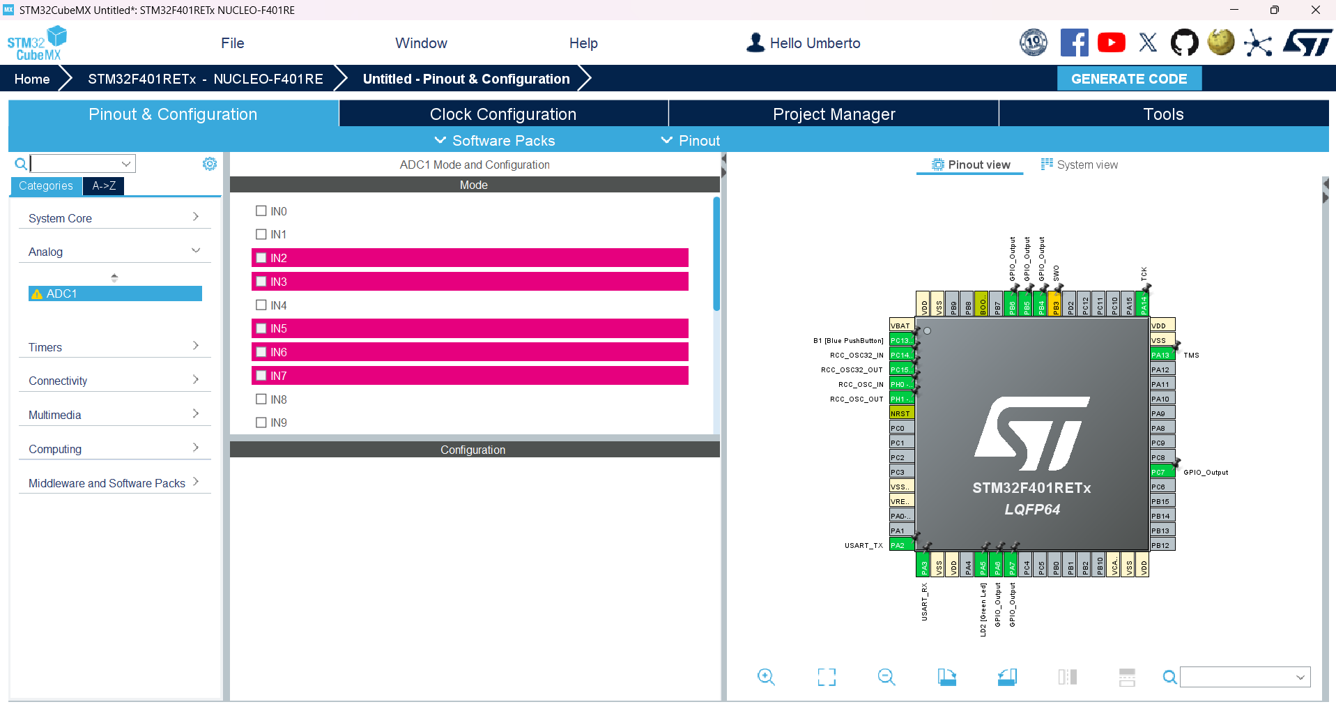
- Click on ADC1 tab and select the analog pins that you have connected.
- Pay attention on select the right value, in this case we have PC_0 , PC_1 respectly situated in :
-
IN10 and IN11. The next view that you have is like this.
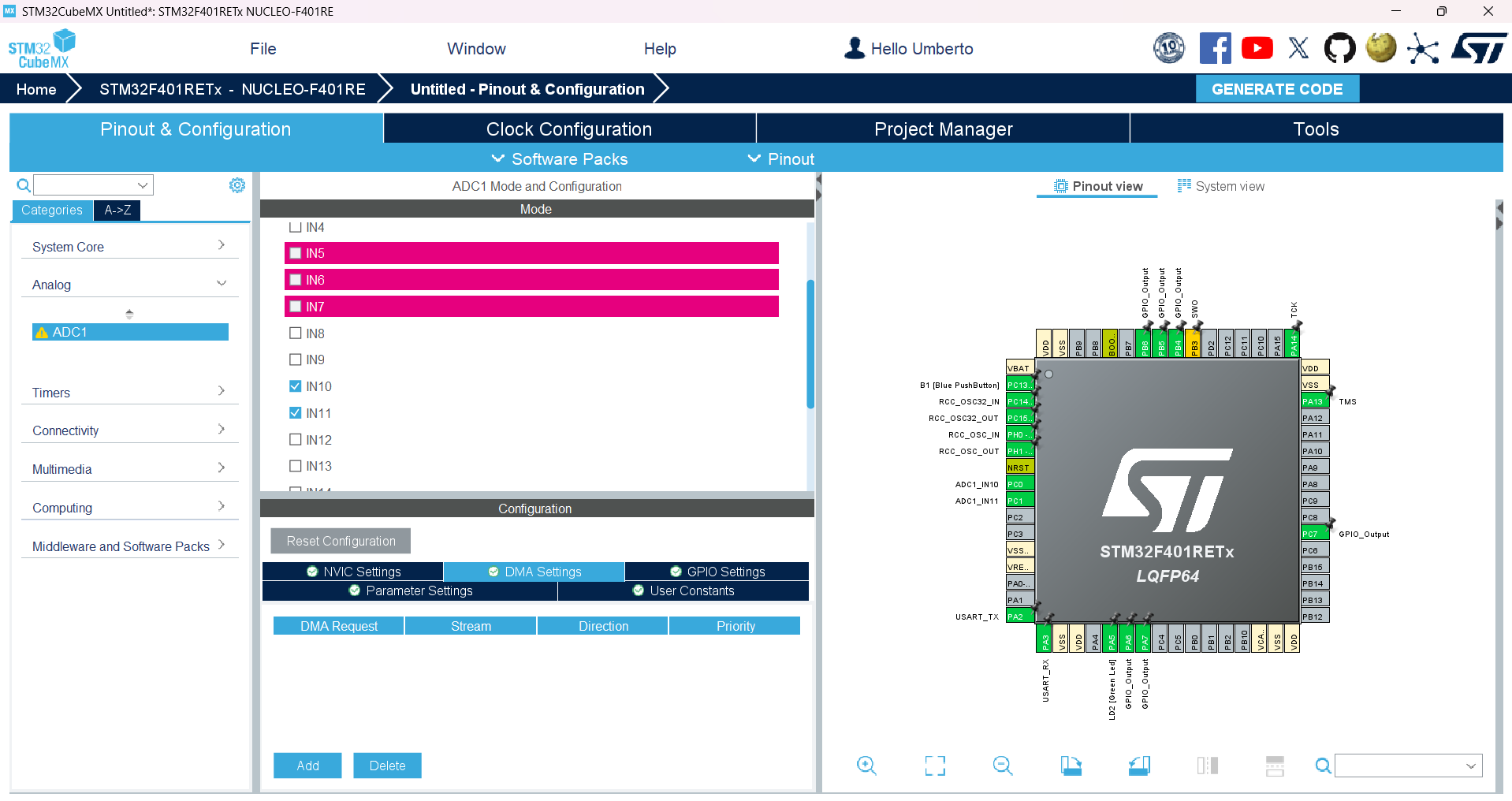
- Now we need to set the Channel Configuration for retrieve the data from the two channels
- Go in the Configuration tab and click on Parameters Setting
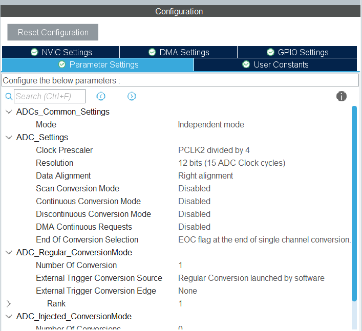
- In the ADC_Settings :
- Click on Scan Conversion Mode and set “Enabled”
- Click on Continuos Conversion Mode and set “Enabled”
- In the ADC_Regular_ConversionMode:
-
Click on Number of conversion and set “2”

- In the Rank 1 :
- Set channel 10
- Set cycles 480 ( the maximum cycle that board support )

- In the Rank 2:
- Set channel 11
- Set the same cycles as we did before 480

2.1 Add ADC1 to DMA
In this section we set the two ADC1 channels to DMA in this way:
- Goes in the Configuration settings as before and click on DMA Settings
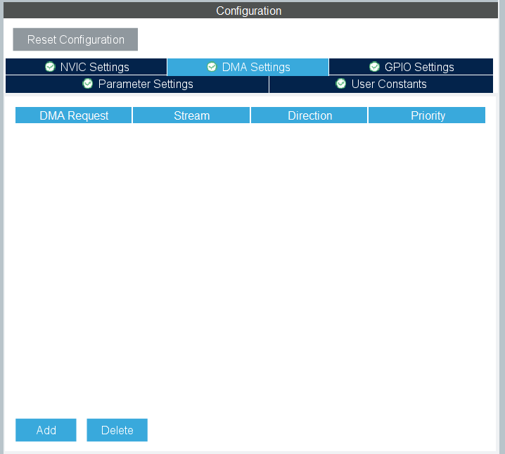
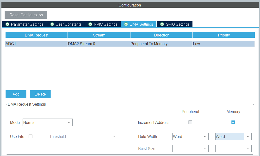
- Click on Add and select ADC1
- After we select the Mode as Normal and the other parameter as Word as we see in the picture
2. GPIO Configuration
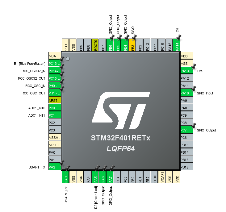
- Configure GPIO pin for joystick button:
- Navigate to the GPIO Configuration tab.
- Set the pin PA_10 as a GPIO input.
- The final configuration look like that
3. Clock Configuration
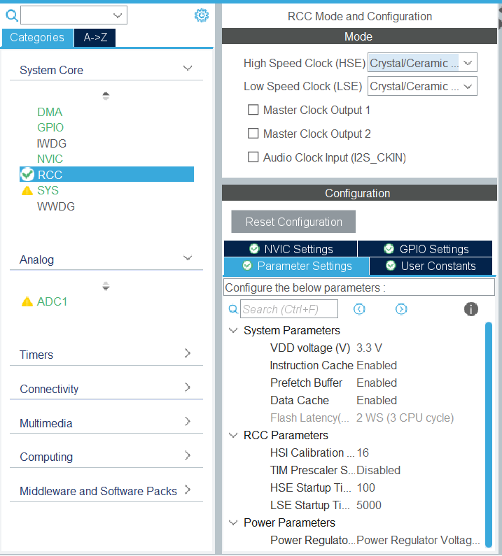
- Ensure that the ADC clock is configured correctly in the RCC settings:
- Navigate to the RCC Configuration tab that is situated in “System Core”.
- Set High Speed Clock HSE as “Crystal/Ceramic Resonator”
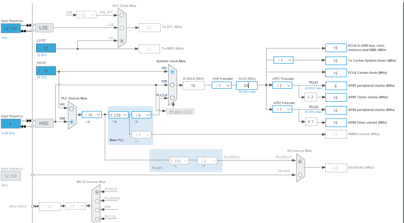
- Clock configuration Tab
- Take a look on the schema and we need to modify:
- In PLL Source MUX select HSE
- In System Clock MUX select HSI and the last value in the HCLK(MHz) select the maximum value that the board support
Now go back