Dino-Game
LCD Display STM32CubeMX Configuration 💡
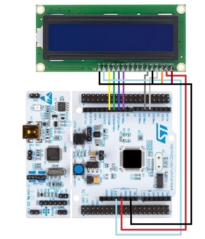
Before to do the configuration on STM32CubeMX take a look of all pin configurations in this table
| LCD Display Pin | STM32 Board Pin > Pin CubeMX Config | Connection Diagram |
|---|---|---|
| VSS | GND |  |
| VDD | 5V | |
| V0 | Potentiometer (for contrast control) | |
| RS | D4 > PB_5 | |
| RW | GND | |
| E | D5 > PB_4 | |
| D4 | D9 > PC_7 | |
| D5 | D10 > PB_6 | |
| D6 | D11 > PA_7 | |
| D7 | D12 > PA_6 | |
| A | 3.3V | |
| K | GND |
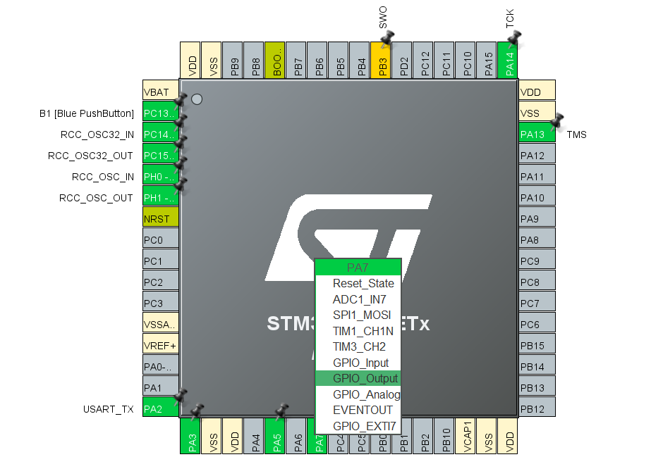
GPIO Configuration:
- Iterate this process for all the pins that you need to configure. This is an example configuration of PA_7 pin as GPIO Output

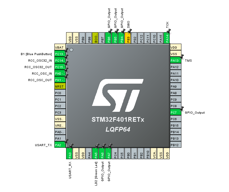
- Configure the pins PB_6, PC_7, PB_4, PB_5, PA_6 as GPIO Output.
Final Result of LCD Configuration Setup
This is how we get from the initial Configuration of LCD display pin.

Now go to Joystick configuration and follow the instructions.